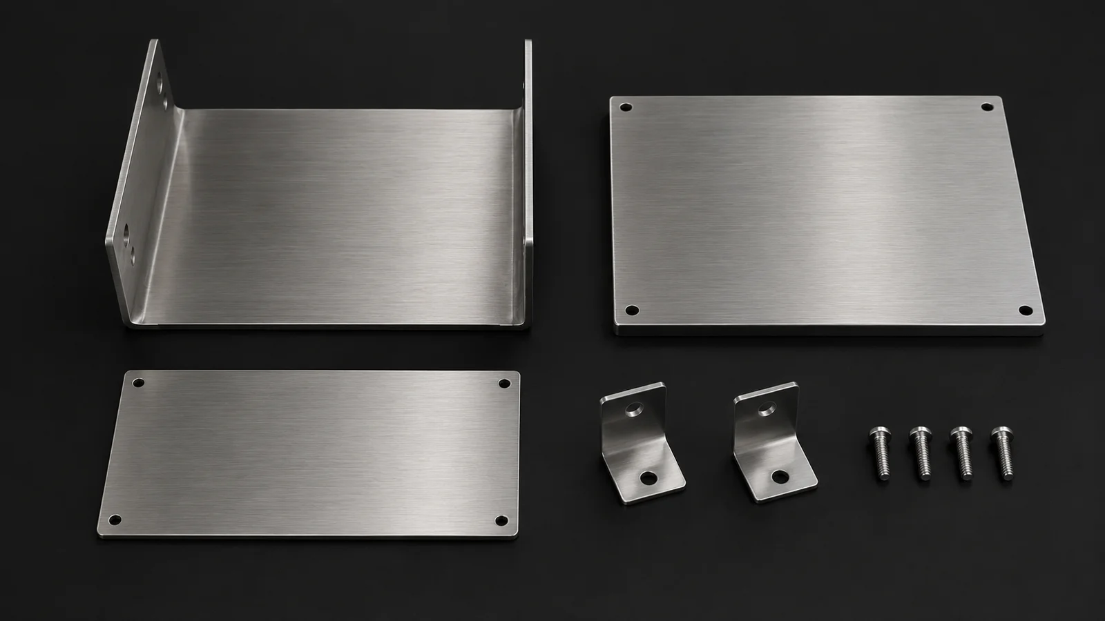
For a custom sheet metal equipment enclosure, outside width, depth and height are only the envelope. The RFQ also needs to show how the body, removable panels, mounting plate and brackets locate against one another, how fasteners are reached, and which parts arrive assembled. A box can occupy the intended space while leaving its equipment impossible to install or remove.
This guide is for OEM buyers and mechanical designers preparing an enclosure fabrication enquiry. It focuses on stainless and carbon steel parts and assembly information. It does not establish an electrical, ingress-protection, thermal or structural rating.
Start with the items that go inside, then follow the proposed assembly sequence: locate the mounting plate, install the brackets and equipment, connect any buyer-installed items, and close the cover or access panel. Review service removal as well as initial installation. Use the supplier’s preferred file format, but preserve each part’s identity and revision throughout the package.
Protolabs identifies tool access and interference at bent corners as enclosure fit issues. A component drawn against a sharp theoretical corner can interfere once the real bend radius is represented; a screw location is not useful if a driver cannot reach it.[1] These are reasons to send the assembly context with the individual part drawings.
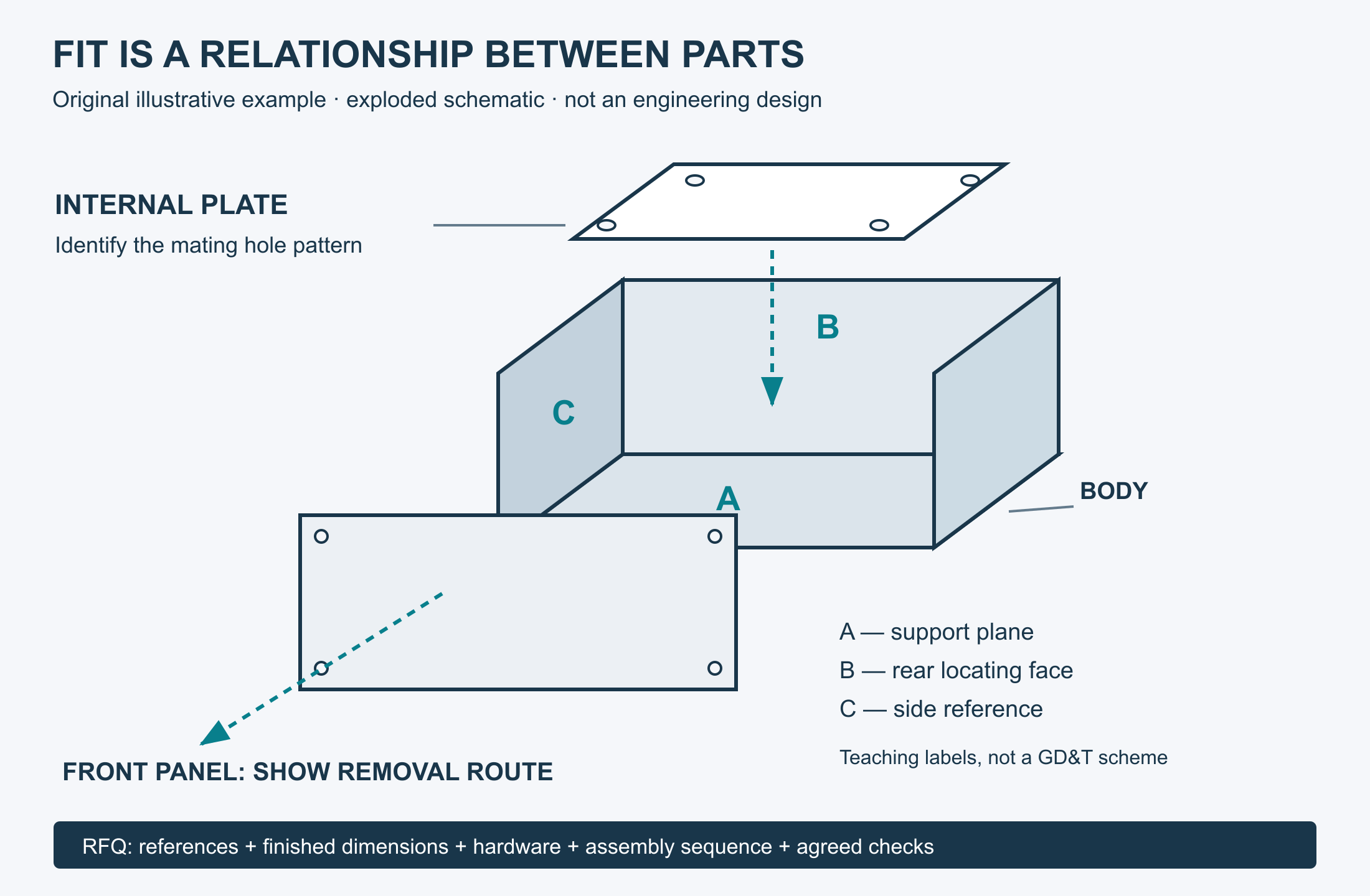
For each assembly step, ask what must already be installed and what will become hidden. If a nut can only be held before the mounting plate is fitted, make that sequence visible. If service requires removing a component through a front opening, show that route with the adjacent equipment in place. A single closed-box rendering cannot answer these questions.
Where the enclosure mounts to a machine frame or guard, agree the mating-part revision with the machinery parts supplier at the same time, so the enclosure and frame are not approved against two versions of one hole pattern.
Mark the surfaces and features that establish position. In the original example below, A is the support plane, B is the rear locating face and C is a side reference. These labels explain the information to agree; they are not a prescribed GD&T datum scheme.
Use an interface drawing to connect the mounting pattern to its locating features. State which holes align with the equipment, which attach the plate to the body, and which attach a bracket to the plate. Give the mating part number and revision next to each pattern. “Four mounting holes” is ambiguous when the assembly contains several four-hole patterns.
Then identify the dimensions that must be checked in the finished assembly. Overall size, plate position and panel opening are separate checks.
Ask the fabricator to review the proposed tolerances and the inspection method against the actual materials, forming, joining and finishing route; the guide to laser cutting tolerances explains why a tolerance class only means something together with its measurement conditions. A tolerance printed on one flat part does not, by itself, define the permissible variation of the complete enclosure. Protolabs publishes separate bands for features on one surface and for measurements across bends, which is why the assembly check has to be named separately from the flat-part check.[4]
Finish can affect assembly as well as appearance. Protocase’s enclosure guide notes that its dimensions are for bare metal and that powder coat requires an additional allowance, and that threaded fasteners are masked before coating while customers may request additional masking.[2] Treat those values as vendor-specific: identify whether critical dimensions apply before or after finishing, and agree any allowance against the selected process rather than copying a universal coating thickness.
| Area | Information the buyer should define | Separate question to resolve |
|---|---|---|
| Visible outer faces | Material, finish reference, texture or colour, grain direction if relevant | Which faces are cosmetic, and how will appearance be compared? |
| Panel edges and openings | Finished opening and mating-part requirement | Is the fit assessed after the specified surface treatment? |
| Threads and selected contact areas | Exact masked locations and extent, if required by the design | Who approves the masking arrangement and checks it? |
| Hidden surfaces | Required treatment and acceptable workmanship | Can hidden faces have a different appearance requirement? |
| Faces needing protection | Protection area and the stage at which it is removed | Is the protection compatible with the agreed fabrication and finishing sequence? |
Do not rely on the phrase “brushed outside” to identify a grain direction across several panels. Add a direction arrow to each relevant face. Likewise, identify a cosmetic weld location separately from a functional joint requirement; the appearance note must not silently change the joining requirement.
Protolabs explains that a 3D model often needs supplementary technical information, including grain direction, insert details and masking locations.[3] The model and drawing should therefore describe the same revision and finish state.
List the actual insert, nut, stud, hinge, latch or other specified component by identifiable part number, quantity and installation location. Distinguish loose hardware from hardware to be installed before delivery. For an access panel, state whether its attachment is a screw, a removable hinge, a fixed hinge or another defined arrangement; the word “door” does not specify the joint.
Self-clinching fasteners include nuts, studs and standoffs pressed into sheet metal.[2] Installation order is part of the specification: Protolabs notes that an insert may need to be installed before or after a plating or coating operation, depending on the finish and the base material, so the hardware note and the finish note have to agree.[1] An RFQ should identify the selected part and installation side, leaving its compatibility and installation requirements to the relevant manufacturer data and agreed fabrication review. Do not turn a generic fastener symbol into permission for an unspecified substitution.
Where the buyer supplies equipment or hardware, state what the fabricator will receive for the fit check: a released drawing, the actual mating part, or an approved checking fixture. Identify who resolves a mismatch and how a later change to the buyer’s component reaches the enclosure drawings.
These are alternative procurement scopes, not standard inclusions. Select one and list exceptions so bidders price the same deliverable.
| Requested delivery | What the order must identify | What must not be assumed |
|---|---|---|
| Fabricated metal parts | Part list, finish state, quantities and individual inspection requirements | Hardware, fitting the parts together or checking against buyer equipment |
| Mechanically assembled enclosure | Metal parts, installed hardware, assembly sequence and agreed fit checks | Electrical work, wiring, sealing performance or a rated complete system |
| Kit for buyer assembly | Which parts and loose hardware are packed together; identification and assembly information | That an assembled fit check was performed before the kit was packed |
Ask the bidder to state the responsibility for each surface treatment and bought-in item, including any outside processing. A request for assembled delivery should also identify what remains open for the buyer’s installation. The enclosure drawing must not imply that equipment installation or system testing is included simply because the equipment appears in the model.
Original illustrative example. An invented instrument enclosure has a body, an internal plate carrying a buyer-supplied module, and a removable front panel. The buyer initially sends an outer-envelope drawing and a panel illustration. No customer project or successful build is represented.
The useful output is an annotated interface drawing and a written list of closed decisions. It is not a larger bundle of pictures. Retain unresolved items visibly on the enquiry and agree who closes each one before release.
A drawing set alone may not carry the assembly intent. The package should let a fabricator identify every part and revision, understand how the parts locate and are checked, and price the same deliverable as the competing bidder. A practical package contains:
The file format is a separate decision from the information content. DXF, STEP and PDF serve different purposes in a bent-part quote, and the DXF vs STEP vs PDF guide explains how the three complement one another. Whichever set you send, use it to carry revision and part identity, not only geometry.
Ask which operations the fabricator will handle in-house and which will be subcontracted while you review its stated laser cutting and sheet metal fabrication services. The answer changes who owns a finish, a hardware installation or a fit check, and it should be written into the quotation rather than assumed from the drawings.
A first-article inspection (FAI) is useful only when the enquiry says what the first article is checked against. For an enclosure, that can mean the interface dimensions in the assembled body, the finished opening after coating, and the agreed hardware positions — not only the individual part dimensions. Write the check list before the order, not after the parts arrive.
A workable fit-check agreement answers four questions. What is measured: overall size, plate position, panel opening or the full assembly interface. With what: calibrated hand tools, a measuring machine, an approved fixture, or the actual mating part. At which stage: bare metal, after finishing, or assembled. And who accepts the result, with what record and what happens if an item is out of tolerance. The agreement should also name the person or role that closes each open interface question.
Change control belongs in the same document: which revision is released, how a change to the buyer’s equipment reaches the enclosure drawings, and whether a change restarts the first-article check. A fit check does not validate electrical, ingress-protection, thermal or structural performance; those sit with the system designer.
Packaging is often treated as a default, but it carries decisions that affect fit and appearance. State the requirements in the RFQ so bids can be compared, and agree details before production rather than at dispatch.
For an assembled enclosure, add the handling method for the assembled unit and state what will be removed before packing. For a kit, state which parts are pre-assembled and which are loose. If inspection records or material documents are required, list them with the delivery scope so they are not requested after shipment.
Send an assembly model, individual part drawings, the interface drawing, BOM, material and thickness requirements, quantities and finish map, the intended assembly and service-removal directions, the drawing register and a short inspection list tied to the mating features, with the delivery scope and any buyer-supplied items.
Submit the package through the quote request page, or email info@zemsteel.com to discuss the enclosure requirements and confirm how to send the drawing package. Request written confirmation of the proposed metalwork and assembly scope, including open fit questions, exclusions and any proposed changes before manufacture. Any required equipment protection, electrical safety or other system performance remains a separately defined validation task.
Send an assembly model in an agreed format, individual part drawings, an interface drawing, the BOM, and a finish map. Add flat patterns such as DXF where the fabricator asks for them. The range of useful formats is explained in the DXF vs STEP vs PDF guide; the file extension does not replace part identity, revision and written requirements.
Put tolerances on the features whose function requires them, then state how they will be measured. A flat-part tolerance does not by itself define assembly variation. Ask the fabricator to review the proposed values against the actual forming and finishing route; background is covered in the guide to laser cutting tolerances.
Either can be correct, but every bidder should price the same scope. The delivery-scope table above shows the different inclusions and exclusions. State which one you are buying and list exceptions, especially hardware, fit checks and packaging.
Define whether critical dimensions apply before or after finishing, identify threads and contact areas that must be masked, and agree who approves the masking. Installation order can depend on the finish, so the hardware note and the finish note must be consistent. Allowances should come from the selected process and supplier, not a copied universal value.
A model is useful assembly context, but it usually needs supplementary information: mating patterns, revisions, finish, hardware and masking locations. Ask the fabricator whether it wants hardware as separate bodies in the model or on a drawing, and state which file is the controlled source.
The buyer and system designer are responsible for the enclosure’s rating and compliance, and any structural or safety conclusion needs the relevant project engineer’s confirmation. A fabrication enquiry can define metalwork, finish, hardware and assembly scope; it does not establish a rating or certify a system.
It should name the characteristics to be checked, the measuring method or checking fixture, the stage at which each check applies, the acceptance record and the person who closes an open item. It should also state how a revision change is handled and whether a change triggers a new first-article check.