TL;DR: Laser cutting holds ±0.2–0.5 mm on steel up to 12 mm as standard shop practice; ISO 9013 is the governing tolerance standard, and most commercial work lands in its range 2–3 classes. Kerf width (0.1–0.3 mm depending on power and nozzle) must be compensated in the drawing. Specify tolerances only where function demands them — every blanket ±0.1 mm you add to a drawing is money you pay twice: once in slower cutting, once in inspection.
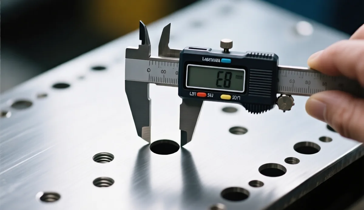
1. What “Standard Tolerance” Actually Means
Ask three suppliers what tolerance they hold and you will hear three confident answers. The honest structure is a hierarchy:
| Level | Typical band (≤12 mm steel) | What it costs |
|---|---|---|
| Commercial standard | ±0.5 mm | Nothing extra — the process default |
| Fine | ±0.3 mm | Slower speeds, fresh consumables, per-batch checks |
| Precision | ±0.1–0.2 mm | Compensated kerf, temperature control, 100% measurement; often better quoted for machining |
Position tolerances on holes run slightly looser than outline dimensions — ±0.3–0.5 mm routine for drilled or cut holes up to ~40 mm plate, loosening with thickness as thermal drift accumulates over pierce cycles.
2. ISO 9013: The Standard That Governs Thermal Cutting
ISO 9013 (Thermal cutting — Classification of thermal cuts) is the reference framework for laser, plasma, and flame cut quality, covering dimensional tolerance, squareness, mean height of profile (roughness), and top edge rounding. Two ideas from it matter for buyers:
- Tolerance depends on workpiece size. The permitted deviation grows with the dimension being measured — a 100 mm part and a 3,000 mm part do not carry the same ± band.
- Quality ranges separate function classes. Range 1–2 suits machined-weld-critical edges; range 3–4 suits structural work where the edge gets welded or hidden. Mapping your parts onto ranges is how you stop over-paying.
Full standard text sits behind the ISO paywall (catalog reference ISO 9013:2017); suppliers should be able to state which range they cut to and show you measurement records backing it.
3. Kerf Width: The Number Everyone Forgets
The beam removes a slot of material — the kerf — typically 0.10–0.15 mm at 3 kW class, 0.15–0.30 mm at 6–12 kW on steel. Consequences that hit real orders:
- Holes cut smaller than drawn. A 10 mm drawn hole comes out ~9.8 mm unless the CNC applies kerf compensation. Good CAM does this automatically — ask, don’t assume.
- Tabs and slots shift. Interlocking parts designed at zero clearance bind after cutting; design 0.3–0.5 mm intentional clearance per joint.
- Strip width drifts. Long narrow strips cut between two passes lose one kerf of width; nest with that in mind.
When you send DXF files, state whether geometry is finished-part (supplier compensates) or already-compensated (cut as drawn). Mixing these assumptions is the most common cause of first-article disputes. Our DXF vs STEP guide covers the file-side details.
4. What Drags Tolerance Down (and What Fixes It)
| Error source | Symptom | Control |
|---|---|---|
| Thermal growth | Dimensions drift over a long run | Warm-up cuts, periodic recalibration, stable shop temperature |
| Plate flatness | Focus errors, tapered edges on bowed plate | Reject/level bowed stock; capacitive height control tuned |
| Worn nozzles/lenses | Widening kerf, beveled edges | Consumable change intervals logged per machine |
| Backlash/wear on drives | Corner rounding, positional scatter | Annual geometric calibration with artifact measurement |
| Heat distortion of the part | Thin parts move after release | Micro-joints, cut sequencing, stress-relief patterns |
Notice the pattern: tolerance is a process discipline outcome, not a machine spec sheet number. A 6 kW machine in a disciplined shop out-measures a 12 kW machine with lazy consumable management.
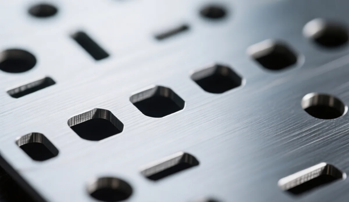
5. When Laser Is Not the Right Tolerance Tool
Honest capability limits save everyone money:
- ±0.05 mm or better → machine the feature after cutting (laser leaves the blank, mill finishes the seat)
- H7 fit holes → cut undersized, then drill/ream
- Optical edge quality on thick plate → consider wire EDM or machining for the critical face
The economic design move is tolerance zoning: ±0.5 mm on outlines, ±0.3 mm only on mating features, machining allowance where fits matter. Drawings zoned this way quote 10–30% cheaper than blanket-tight drawings for identical function.
6. Verifying Tolerance at Receiving
Spot-check discipline that catches 90% of problems:
- First article per batch — full dimension check against drawing, recorded
- Random 3-piece sample per lift — critical mating dimensions only
- Kerf audit on holes — pin-gauge the most-used hole size; systematic −0.2 mm means compensation is off
- Squareness — check one diagonal pair per part family; consistent error means machine geometry, not operator, is at fault
For structural work pairing cut plates with welded assemblies, our guide on cut-to-size ordering covers what to put in the purchase order so tolerance obligations are contractual, not aspirational.
FAQ
What tolerance does laser cutting hold on steel plate?
±0.5 mm is standard commercial practice up to 12 mm; ±0.3 mm is achievable with care, and ±0.1–0.2 mm is possible on thin material with compensation and measurement — at sharply rising cost.
What is the ISO standard for laser cutting tolerances?
ISO 9013:2017 — Thermal cutting, classification of thermal cuts. It defines tolerance ranges and edge-quality classes that apply to laser, plasma, and flame cutting alike.
Why are my laser cut holes smaller than the drawing?
Kerf compensation is missing or misconfigured: the beam removes a 0.1–0.3 mm slot, so holes cut smaller than drawn unless the CAM offsets the path. Ask your supplier to confirm compensation policy before first articles.
Does plate thickness affect laser cutting tolerance?
Yes. Thick plate amplifies focus sensitivity, pierce drift, and taper, so the achievable band widens with thickness. Hold tight tolerances on thin and medium plate; design looser or machine-finish above 20 mm.
How should tolerances be marked on drawings for laser cutting?
Zone them: general tolerance block (e.g., ISO 9013 range 3) for outlines, explicit tight tolerances only on functional features, and a note stating geometry is finished-part size with supplier kerf compensation.
Drawing ready for a tolerance sanity check? Send it through our quote form — we flag tolerance conflicts before cutting, not after, and quote the tolerance tiers separately so you see what each band costs.
References
- ISO. “ISO 9013:2017 Thermal cutting — Classification of thermal cuts — Geometrical product specification and quality tolerances.” ISO, 2017. iso.org/obp (ISO 9013) (accessed Aug 29, 2026).
- ISO. “ISO 2768-1:1989 General tolerances — Part 1: Tolerances for linear and angular dimensions without individual tolerance indications.” ISO, 1989. iso.org/obp (ISO 2768-1) (accessed Aug 29, 2026).
- Zemlaser. Quality records, dimensional inspection logs, accessed Aug 29, 2026.(第一手质检数据,本网站)