You’ve designed the part. You have the CAD file. You need a laser cutting quote. But should you send a DXF or a STEP file? Sending the wrong format can add days of back-and-forth to your quoting process — and in B2B manufacturing, time is literally money. At Zemlaser, we process 50+ RFQs daily from OEM buyers across 20 countries. Here is what our engineering team actually needs from your file.
DXF (Drawing Exchange Format): The 2D Workhorse
DXF is a 2D vector format developed by Autodesk in 1982 for AutoCAD interoperability. Despite being over 40 years old, it remains the most widely used format for flat-pattern laser cutting — and for good reason.
What DXF Does Well
- Laser-ready geometry: DXF describes parts as lines, arcs, circles, and closed polylines — exactly what a laser cutting machine CAM software needs to generate toolpaths. No conversion. No interpretation.
- Nesting direct: DXF files import directly into nesting software (sheet nesting optimization) for material utilization calculations. This is why we can quote your material cost within hours.
- Small file size: A typical bracket DXF is 50-500 KB. Easy to email. No FTP required.
- Universal: Every laser shop, plasma table, and waterjet in the world reads DXF. No format lock-in.
DXF Pitfalls to Avoid
- Open contours: The most common DXF error we see. A polyline that looks closed but has a 0.01 mm gap will fail to generate a toolpath. Our engineers catch these, but they add quoting time.
- Wrong scale: Always export at 1:1 in millimeters. We receive DXF files drawn in inches, centimeters, or even pixels. A 25.4x error on a 2-meter part is an expensive mistake.
- Annotations on cutting layer: Dimensions, title blocks, and notes on the same layer as cutting geometry cause CAM errors. Put them on separate layers or remove them before sending.
- Splines: Complex spline curves do not always translate cleanly to G-code arcs. Convert to polylines with reasonable tolerance (0.01 mm) before exporting.
Best for: Flat parts — brackets, flanges, gussets, panels, shims, washers. Any part that can be fully described in 2D.
STEP (ISO 10303): The 3D Standard
STEP (Standard for the Exchange of Product Data) is an ISO standard (ISO 10303) for 3D product data. Unlike DXF, STEP captures solid geometry, assembly relationships, and product manufacturing information (PMI).
What STEP Does Well
- 3D geometry: STEP describes the full solid model — not just the outline. Our engineers can rotate, section, and measure your part in 3D before quoting.
- Bend information: For parts requiring laser cutting plus bending, STEP shows bend angles, directions, and radii. We can assess flat-pattern development and flag features that will deform during forming.
- Manufacturability assessment: With a STEP file, we check hole-to-edge distance, minimum bend radius vs. material thickness, and feature accessibility — before cutting a single part. This catches design issues that DXF reviews miss.
- Multi-process parts: If your part goes laser cut, bend, weld, machine — the STEP model is the single source of truth across all processes.
- Assemblies: STEP supports multi-body assemblies. We can quote individual components and the assembled weldment from one file.
STEP Limitations
- Larger files: A STEP model is typically 1-50 MB vs. a DXF at 50-500 KB.
- Not nesting-ready: STEP models need to be flattened to 2D profiles before nesting. This is an extra step in our CAM workflow that DXF avoids.
- Version compatibility: STEP AP203, AP214, AP242 — different application protocols carry different information. AP242 includes PMI (GD&T, surface finish); AP203 does not. We read all three.
Head-to-Head Comparison
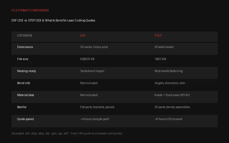
| Criterion | DXF | STEP |
|---|---|---|
| Dimensions | 2D only | 3D solid model |
| File size | 50-500 KB | 1-50 MB |
| Nesting-ready | Yes | No (needs flattening) |
| Bend info | No | Yes |
| Standard | De facto (Autodesk) | ISO 10303 |
| Material data | No | Yes (AP242) |
| Quote turnaround | ~4 hours (simple part) | ~8 hours (3D review) |
| Best for | Flat parts, simple profiles | 3D parts, bends, assemblies |
Common File Preparation Mistakes That Delay Quotes
After processing 10,000+ customer files, these are the issues that most frequently add quoting time. Fix them before you send and you will typically get a quote back in under 4 hours.
Missing Material Specification
A DXF with no material callout is the single biggest quoting bottleneck. We need to know: grade (304, 316L, Q235, 6061-T6), thickness in millimeters, and surface finish (mill, No.4, No.8, PVD). Without this, our engineers have to ask — and every round-trip email adds 12-24 hours. Include material specs in the filename, a separate PDF, or email body.
Tolerances Not Called Out
If your drawing has no tolerance block, we default to our standard laser cutting tolerance of ±0.1 mm for features under 300 mm and ISO 2768-m for general dimensions. If you need ±0.05 mm on a specific bore or edge, mark it explicitly. We can hold it — but we need to know.
Threaded Holes and Tapped Features
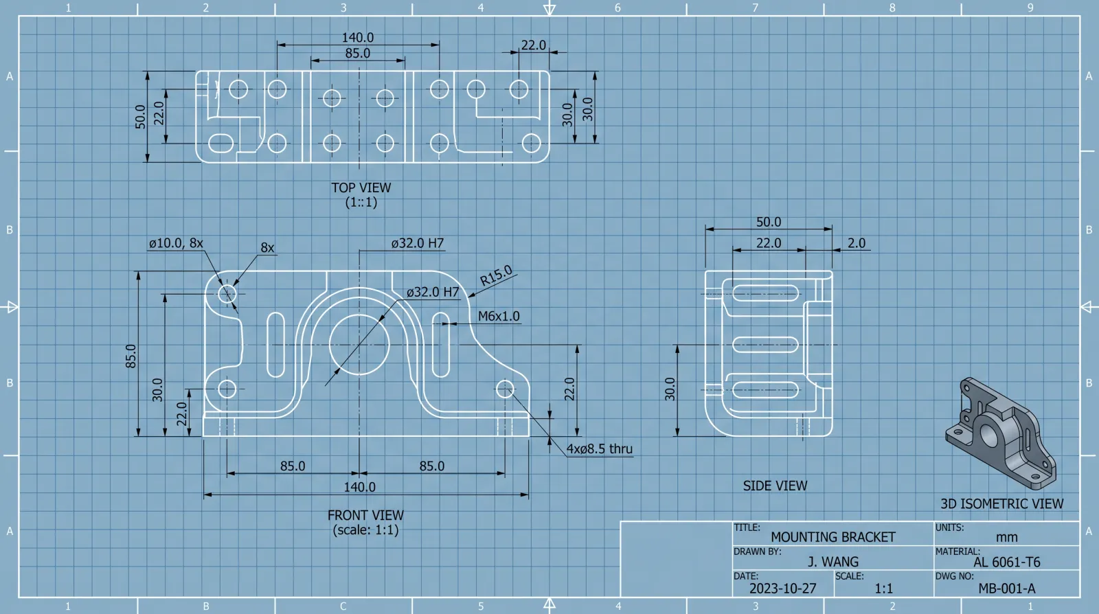
Laser cutting cannot produce internal threads. If your part has holes that need tapping (M3, M4, M6, etc.), note the thread size and pitch on your drawing. We handle tapping as a secondary operation after cutting — but only if we know about it at quoting stage. Retrofitting tapped holes after parts are cut adds cost and lead time that could have been avoided.
Multiple Parts in One File
We love receiving multi-part assemblies. But please separate individual components onto labeled layers or sheets. A single DXF with 15 unlabeled outlines on one layer requires our team to manually separate and identify each part — adding quoting time. Best practice: one part per layer, layer name = part number, all at 1:1 scale.
Which Should You Send to Zemlaser?
The answer depends on your part — here is our engineering team recommendation:
Send DXF when:
- Your part is flat (no bends, no 3D features)
- You already have a nested layout or want us to optimize material utilization
- You need the fastest possible quote turnaround
- You are reordering a part we have cut before
Send STEP when:
- Your part has bends, multiple processes, or assembly steps
- You want a manufacturability review (we will flag issues before cutting)
- This is a first-time RFQ and you want our engineers to fully understand the design intent
- You are quoting a multi-part assembly or weldment
Send Both for the Best Experience
The fastest, most accurate quotes come when you send both DXF + STEP. The STEP file gives us 3D design intent and bend information. The DXF file lets us nest and price material immediately. This combination typically delivers a quote in under 4 hours. For high-volume production runs, also include a PDF drawing with tolerance callouts and material specifications.
What Zemlaser Accepts
We accept files in all common CAD formats. Our manufacturing engineering team works with whatever you have:
.dxf AutoCAD DXF.dwg AutoCAD DWG.step / .stp STEP AP203/214/242.iges / .igs IGES 5.3.pdf Drawing / TolerancesNo CAD file at all? Send a hand sketch with dimensions — we will create the DXF for you. Free CAD support is included with every quote. This is part of what factory-direct means at Zemlaser: no middleman, no red tape, just an engineering team that solves problems.
For a deeper look at how we cut your parts after we receive your file, read our Fiber Laser vs Plasma vs Waterjet comparison and browse our materials reference for grade and thickness specifications.
Upload Your Drawing – Free 24h Quote
DXF . DWG . STEP . IGES . PDF accepted | 1-piece MOQ | No obligation
Frequently Asked Questions
Can I send a PDF drawing instead of a CAD file?
Yes. If your PDF includes dimensioned views at 1:1 scale (or clearly stated scale), our engineers can recreate the geometry. For simple flat parts, this adds minimal time. For complex 3D parts with bends, a STEP file is strongly preferred — recreating 3D geometry from 2D PDF views takes longer and introduces interpretation risk.
My DXF file will not open – what should I check?
The most common causes: (1) The file was exported at the wrong DXF version — use AutoCAD 2010 DXF or later. (2) The geometry contains blocks or XREFs that were not exploded before export. (3) The file uses splines that need to be converted to polylines. If your file will not open, email it anyway — our CAM software handles most DXF variants, and if it cannot, we will tell you exactly what to fix.
What STEP application protocol should I use?
STEP AP214 or AP242 are preferred because they include color, layer, and GD&T information. STEP AP203 works fine for basic 3D geometry but carries less metadata. All three are accepted. If your CAD software gives you a choice, pick AP242 — it is the most complete.
Do you sign NDAs for proprietary designs?
Yes. All customer CAD files are treated as confidential intellectual property. We sign mutual NDAs as standard practice, and our privacy policy specifically covers CAD data protection (Section 3: CAD File and IP Protection). Your designs are never shared with third parties, used as samples for other customers, or retained beyond the project lifecycle without your written consent.