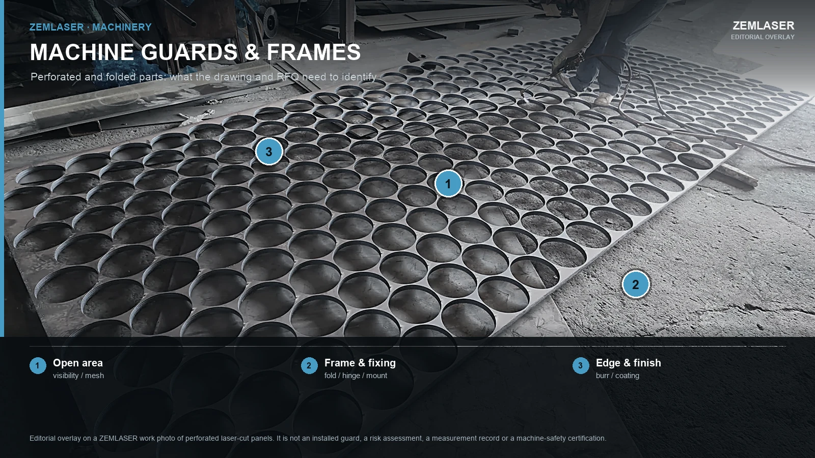
Custom laser-cut machine guards and frames are specified by function before fabrication: which hazard the guard separates, whether it is fixed or movable, the opening size the risk assessment requires, and how it is fixed, removed and finished. Safety design and compliance stay with the machine builder and employer; the fabrication package converts that design into cut, bent and finished parts.
This guide helps equipment builders, plant engineers and procurement staff turn a guard concept into a manufacturable drawing and a comparable RFQ. See our machinery industry page for how these parts fit into equipment building, and laser cutting and fabrication services for the scope.
Perimeter guards, fixed covers, interlocked doors and viewing panels use the same cutting and bending operations but ask different questions of the drawing. A fixed cover is a plate with flanges and mounting holes; an interlocked door is a frame with hinge positions, a latch and a switch bracket, stiff enough not to sag into it. If the RFQ does not say which type you are buying, suppliers quote a plate and the bracket becomes a redesign.
| Guard type | Usually laser cut or bent | Your designer must decide | Common RFQ gap |
|---|---|---|---|
| Perimeter guard or fence panel | Posts, infill frame, feet, brackets, gate posts | Fixed or movable gate, opening size, whether access needs interlocking | No risk-assessment reference for the opening; gate and fixed panels mixed on one drawing |
| Fixed guard or cover | Panel, edge returns, stiffeners, brackets, viewing aperture | Removal frequency and tools; reach distances; ventilation openings | Machine mounting points not dimensioned |
| Interlocked movable guard | Door panel, hinge and latch mounts, stiffener frame, switch bracket | Which interlock device, how it is mounted and actuated | Switch make and model left open, so the bracket is designed after the parts are cut |
| Viewing panel or window | Aperture frame, clamp ring, fixing holes | Window material and thickness, fixing method, site replaceability | Window thickness not given, so the aperture cannot be checked against it |
| Guard frame or machine frame | Tube or bent-plate frame, gussets, feet, brackets | Rigidity, anchoring or levelling, integration with the machine base | Squareness or diagonal callout missing; floor interface not specified |
Two scope decisions belong before the drawing is issued: cut-and-bent parts, a welded frame or an assembled guard; and who supplies mesh, window sheet, hinges, latches and fasteners. A quote silent on those items is not comparable.
In the United States, 29 CFR 1910.212 requires machine guarding to protect operators and other employees from hazards such as the point of operation, ingoing nip points, rotating parts, flying chips and sparks, and names barrier guards as one example.[1] It does not give a universal mesh size. One concrete limit covers a specific case: where fan blades are less than seven feet above the floor or working level, the guard openings must be no larger than one-half inch.[1] That is a fan rule, not a default for every panel.
Reaching through openings is addressed by ISO 13857:2019, which establishes safety distances to prevent machinery hazard zones being reached by upper and lower limbs.[3] Values depend on opening shape and size and on distance to the hazard; its scope covers people of 14 and older, with additional upper-limb information for children over three where reaching through openings must be addressed.[3] The full text is paid and not reproduced here; your designer applies the current edition or a local equivalent and gives you the opening.
The drawing should state the opening dimension and its source, whether a risk assessment, a standard reference or a customer specification. A fabricator should not choose mesh from stock: the same perforated sheet can be safe on one machine and inadequate on another.
After that decision the panel is a trade-off: open area affects visibility, airflow, coolant mist and how easily chips and dirt pass through; stiffness falls as open area rises, so wide panels need returns or stiffeners rather than bigger holes.
Cutting cost rises with cut length, so a dense pattern of small holes can cost more than a plain panel with a few large apertures; for regular high-volume patterns, punching is often cheaper, as compared in perforated panels: laser cutting vs punching. To calculate how open the panel should be, see open area in laser-cut perforated patterns.
Expanded metal and woven mesh are common alternatives: laser cutting makes the frame and fixing holes, while the mesh is bought as stock sheet. Say whether the supplier buys it. Visibility needs a drawing note too: mark the operator position and controls, and keep solid bands out of the sight line. Where an operator must watch the process continuously, a window is usually better than fine mesh. Plan the aperture, window material, clamp ring and replacement access together; the window sheet is outside the laser shop’s scope, the cut aperture is not.
Laser cutting produces a flat blank; bending is a second process, and the flat pattern is not simply the formed drawing unfolded. The bend allowance depends on material, thickness, inside radius and tooling, so a supplier given only formed dimensions must reconstruct the blank. Supply a flat pattern for approval, or ask for one before cutting; a formed drawing with bend lines, direction and inside radius is the safer first document.
Call out tolerance where it matters. General tolerances cover the rest, but dimensions that control fit, hinge alignment, interlock actuation and window clamping need their own limit. Our guide to laser cutting tolerances explains how cut tolerance, hole position and bend angle interact; the drawing task is to nominate critical dimensions rather than expect a general note to cover them.
Holes near a bend are a frequent fit problem: material stretches and thins around the bend, so a hole too close to the bend line distorts and the fastener no longer sits flat. Rather than assume a rule of thumb, ask the fabricator for the minimum hole-to-bend distance for the material and tooling they will use. The same applies to slots and cut-outs that must stay flat for a gasket or window clamp.
Fastener strategy is decided before cutting. Clearance holes, tapped holes, weld nuts, rivnuts and self-clinching fasteners change the hole size and the order of operations. If the fabricator supplies fasteners, list standard, size and material; if you supply them, state which holes they go into.
Hinges are where guards most often fail to fit. Piano, butt and lift-off slip hinges need different mounting details, and the choice depends on whether the panel swings open for service or comes off. Weld-on hinges cannot be adjusted after welding; bolt-on hinges need fastener access. For multi-panel guards, locate all hinge axes from one datum so the panels line up, which usually means a jig or a checked frame. State the hinge type, or ask for a proposal with panel weight and opening angle given.
Frames raise the assembly question: a welded frame carries its squareness from the shop, a flat-pack frame carries it to your floor. Give a squareness or diagonal tolerance where the guard must line up with the machine, and say whether the frame arrives welded, trial-assembled or loose. If the guard is assembled before shipping, agree the trial fit, including a full swing of every movable panel.
Finish is usually chosen last and causes expensive rework, because it changes fits, threads and appearance after the parts are already correct. Start from the environment and the handling, then pick the process.
Whatever the process, deburr before coating: a burr can show through powder coat, damage it in handling or cut the person removing the guard. Cleaning belongs in the specification too, because oil, dross and weld spatter become coating defects.
Environment drives the choice more than appearance. A dry indoor shop, a coolant-mist cell and a washdown area are three different problems; guards in food and beverage plants are cleaned with chemicals, so finish and edge questions overlap with our food and beverage industry page.
A drawing a fabricator can quote without guessing answers the same questions every time. This checklist is not a substitute for your designer’s dimensioning standard.
| Callout | What to write | Why it matters |
|---|---|---|
| Material and thickness | Grade and standard, thickness with unit, surface condition | “Mild steel” or “2 mm” alone does not define what is quoted |
| Flat pattern or formed geometry | Formed dimensions plus bend lines, or an approved flat pattern | The blank and the formed part are different drawings |
| Critical dimensions and datums | Datums, critical features with their own tolerance, and the fit they control | General tolerances do not protect hinge alignment or interlock actuation |
| Bends | Inside radius, angle, direction, sequence where it matters | Radius and tooling determine the flat pattern |
| Holes and cut-outs | Size, position, purpose, hole-to-bend limits | Hole size and coating sequence decide whether the fastener fits |
| Opening or mesh pattern | Opening dimension, layout, orientation, requirement reference | The opening is a safety decision, not a stock choice |
| Welds | Symbols, visible or hidden, dressing and inspection | Welding affects squareness, coating appearance and cleaning |
| Finish | Process, colour reference, gloss, masking, touch-up | Finish changes fits; masking agreed late becomes rework |
| Assembly and supply scope | Cut and bent only, welded frame or assembled guard; who supplies hardware | Two quotes with different scope are not comparable |
Send the drawing set with the RFQ: DXF or DWG for the flat parts, STEP for formed geometry where you have it, and a PDF drawing with a revision block as the controlling document. Ask each supplier to state which file and revision was priced; if the formats are new to you, DXF vs STEP for laser cutting explains what each carries.
The RFQ should also state quantity per part and per assembly, material, thickness, finish, assembly scope, hardware supplied by each side, inspection and documentation, packing, destination and date. Ask every supplier to list exclusions and deviations; a quote that says “as drawn” without naming the revision is a risk at the first change order.
Agree the inspection basis before the order, because a guard is a fit-up part rather than a catalogue item. A first-article check covers critical dimensions, hole positions against the mating part or a pin gauge, bend angles, frame squareness and diagonals, hinge positions relative to each other, latch engagement and, where specified, the window aperture against the window. If the guard is assembled, include a full swing of each movable panel and a check that no panel touches the machine frame at the end of travel.
Finish inspection is visual and, where a specification exists, measured; record the result and any approved deviation rather than a verbal “it looks fine”. Packing decides whether the finish arrives intact: interleave coated panels, brace frames so strapping does not pull them out of square, and label each package with part number, assembly, revision and quantity. Carbon steel parts travelling by sea need a corrosion-protection plan agreed in the RFQ; coated and stainless parts still need protection from abrasion. If a large frame needs a crate rather than a pallet, say so early, because packing changes shipping cost.
A laser cutting supplier manufactures to the drawing. It does not perform the risk assessment, choose the guard type, set the safety distance, select interlocks or validate the machine’s safety functions; those are machine builder and employer responsibilities.
Ask which requirement a supplier claims to meet, which document records it and who declares it. “The guard is compliant” without that answer is a sales sentence, not a compliance statement. Regulated-market projects need project engineer confirmation.
Send a DXF or DWG for the flat parts, a STEP file for formed geometry, and a PDF drawing with a revision block as the controlling document.
That is a risk-assessment decision, not a stock choice. The opening must prevent access to the hazard zone for the people who can reach it; ask your designer for the dimension and its basis.
Laser cutting produces the flat blank, and the holes can be cut in the same program. Bending is separate, so the flat pattern has to include the bend allowance.
Put tolerance on the dimensions that control fit: frame squareness or diagonals, hinge and latch positions, and machine mounting points. Agree a general tolerance for the rest.
Both are possible. A welded frame carries its squareness from the shop; flat-pack shifts the tolerance stack to your assembly floor and can reduce packing volume.
The fabricator can cut the door, frame, hinge mounts and device bracket, and fit hardware you specify. Interlock selection, wiring and validation stay with the machine builder.
Agree the critical dimensions, fit-up trial and finish checks before production, then record the results. Packing should protect the finish, keep frames square and label packages.
Scope note: this is a procurement and fabrication checklist, not a risk assessment, a guard design manual or a conformity statement for any machine, guard or supplier. Obtain the current editions for design work.
If a guard or frame drawing is ready, send the files, material, thickness, finish, assembly scope and destination through the quote page and ask for exclusions and deviations in writing, so the offers you compare cover the same scope.