Steel embed plates — also called cast-in plates, anchor plates, or weld plates — are flat steel components cast into concrete so that structural steel, railings, cladding, or equipment can be welded or bolted to the structure later. If you are sourcing custom embed plates from China, this guide covers the sizes, steel grades, stud options, coatings, tolerances, and lead times you need to specify before you request a quote.
At Zemlaser, we laser-cut and fabricate custom embed plates from our factory in Taiyuan, China — with a 1-piece minimum order, tolerances held to ±0.1 mm, and as fast as 7-day FOB Tianjin. Here is what a buyer needs to know.
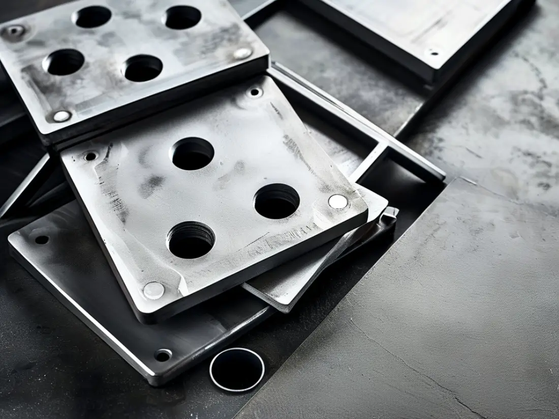
Custom laser-cut steel embed plates, drilled and ready for stud welding.
What Is a Steel Embed Plate?
An embed plate (US term: “embed” or “embed plate”; UK/Australia: “cast-in plate”) is a steel plate positioned in formwork and cast flush with the concrete surface. Once the concrete cures, the exposed plate face becomes a fixing point. Common uses include:
Structural steel connections — beams and columns welded to the concrete frame
Facade and cladding support — brackets bolted or welded to embeds
Precast concrete panel connections — plate-to-plate welding between panels
Handrails, canopies, and equipment mounts
Anchorage into the concrete is provided by headed studs, deformed bar anchors (DBA), or welded rebar on the back face. The plate itself is almost always laser-cut for a clean, square, dimensionally accurate edge — which is where a fiber laser factory has a clear advantage over sheared or flame-cut plate.
Embed Plate vs Anchor Plate vs Weld Plate: Terminology
Buyers in different regions use different names for closely related parts. When you request a quote, spelling out what you mean avoids costly mismatches:
Embed plates are not standardized worldwide — they are almost always custom to the project’s structural drawings. That said, most fall within these ranges:
The table below covers the most common embed plates specifications our customers request:
Parameter
Typical range
Plate thickness
6 – 25 mm (heavier for high-load connections)
Plate size
100 × 100 mm to 600 × 600 mm (larger on request)
Steel grade (carbon)
ASTM A36, Q235, S275, S355
Stud diameter
10 – 25 mm headed studs
Anchor length
100 – 300 mm, per pull-out requirement
Carbon steel grades such as ASTM A36 and S355 are standard because embeds are structural and are welded on site. Zemlaser cuts carbon steel plate up to 80 mm and stainless up to 150 mm, so heavy base-connection embeds are well within capacity. For material selection help, see our laser cutting materials guide.
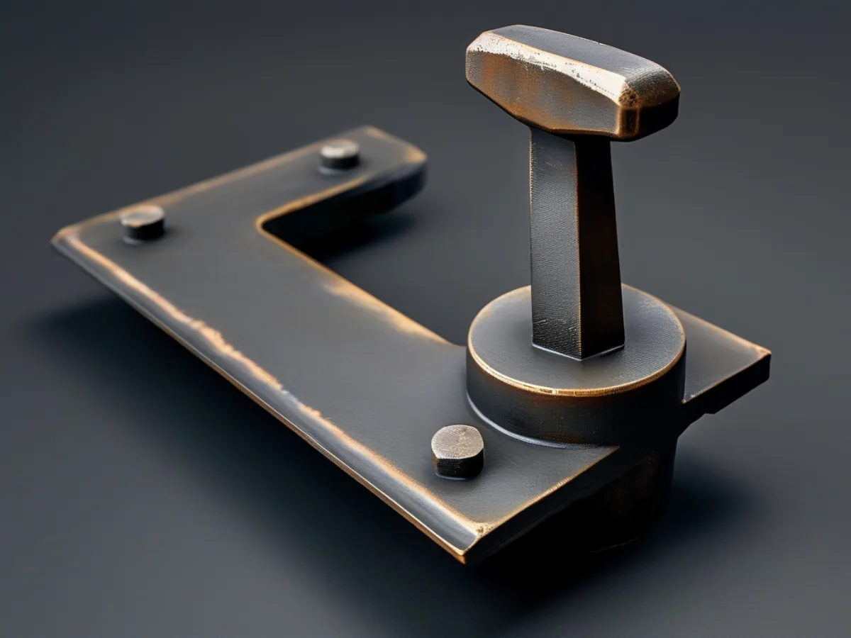
Anchor plate with welded headed studs for pull-out resistance in concrete.
Coatings: Galvanized vs Bare Steel
Because embed plates sit in concrete and are often exposed to moisture, corrosion protection matters:
Bare (black) steel — lowest cost; acceptable for fully encased, dry interior conditions.
Hot-dip galvanized (HDG) — the standard for exterior, marine, or high-humidity structures. Galvanizing after fabrication protects the plate and the exposed studs.
Stainless steel embeds — used in aggressive chemical or coastal environments where even galvanizing is insufficient.
Specify the coating up front: galvanizing adds lead time and must be planned around stud welding. If you are unsure, tell us the exposure conditions and we will recommend a spec.
Tolerances and Quality
Embed plates fail their purpose if holes, edges, or overall dimensions drift. Laser cutting delivers the accuracy structural connections demand:
Edge and hole position: ±0.1 mm on the laser-cut plate
Squareness: true 90° edges, no bevel or dross from flame cutting
Stud placement: jig-welded to the drawing for consistent anchorage
Traceability: mill certificates for the plate on request
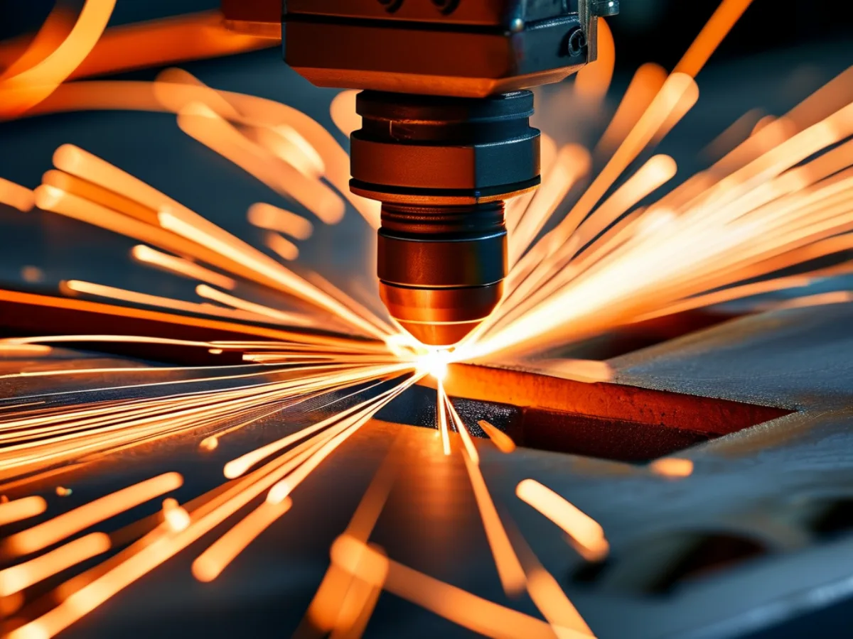
Fiber laser cutting carbon steel plate — clean, square edges to ±0.1 mm.
How to Order Custom Embed Plates from China
The process is straightforward when your drawings are ready:
Send your drawings — DXF, DWG, STEP, or a marked-up PDF with plate size, thickness, grade, stud layout, and coating.
Receive a quote — factory-direct pricing, typically within 24 hours, with no middleman markup.
Sample or first-article approval — 1-piece MOQ means you can order a single plate to verify before committing to volume.
Production and QC — laser cutting, stud welding, galvanizing, and inspection.
Shipping — as fast as 7-day FOB Tianjin.
Because Zemlaser is a factory — not a trading company — you talk directly to the engineers who cut and weld your parts. That means real feasibility checks, real lead times, and pricing without a hidden layer. Ready to price your project? Get a free embed plate quote.
Frequently Asked Questions
Who can laser-cut custom anchor plates for construction?
Zemlaser fabricates custom embed and anchor plates in China with a 1-piece minimum order. Plates are laser-cut to ±0.1 mm, fitted with headed studs or deformed bar anchors, and available bare or hot-dip galvanized, with mill certificates on request.
What is the difference between an embed plate, an anchor plate, and a weld plate?
An embed plate is any steel plate cast into concrete. An anchor plate specifically has welded anchors (studs or rebar) for pull-out resistance. A weld plate is an embed left flush so steel can be welded to it later. In practice the terms overlap and depend on region.
Can I order custom steel embed plates with welded headed studs?
Yes. We laser-cut the plate, then jig-weld headed studs or deformed bar anchors to your drawing for consistent placement. Stud diameter, length, and layout are all made to spec, and the assembly can be hot-dip galvanized afterward.
What steel grade and thickness are used for concrete embed plates?
Most embed plates use carbon steel grades such as ASTM A36, S275, or S355, in 6–25 mm thickness. Heavier connections use thicker plate. Zemlaser cuts carbon steel up to 80 mm, so high-load embeds are within capacity.
How fast can I get embed plates shipped from China?
Standard lead time is as fast as 7 days FOB Tianjin, depending on quantity, coating, and stud welding. Galvanizing adds a few days. Send your drawings for a firm lead time with your quote.
Get a Quote for Your Embed Plates
Whether you need a single prototype embed plate or a production run of custom embed plates for a precast or structural steel project, Zemlaser can cut, weld, galvanize, and ship custom embed plates factory-direct from China. Explore our steel embed plate fabrication service, or send your drawings today for a free 24-hour quote. For related structural work, see our structural steel laser cutting and precast concrete mould services.
Need Custom Embed Plates?
Send your drawings for a free 24-hour quote — factory-direct from China, 1-piece MOQ, as fast as 7-day FOB Tianjin.
DXF vs STEP: Which File Format for Laser Cutting Quotes?
PublishedJuly 2026 Read5 min
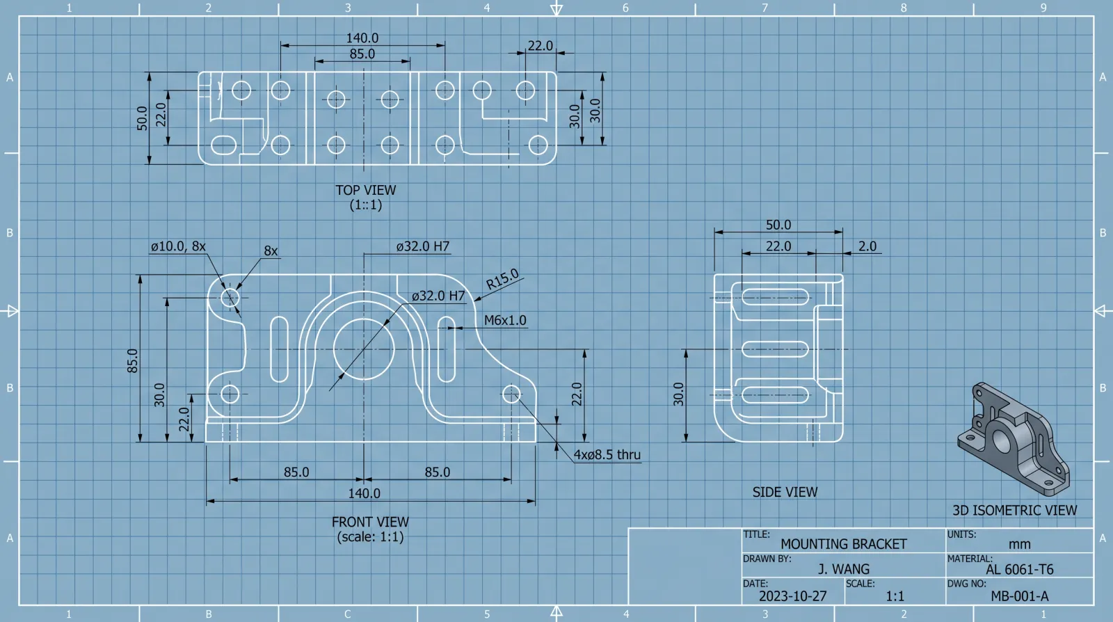
You’ve designed the part. You have the CAD file. You need a laser cutting quote. But should you send a DXF or a STEP file? Sending the wrong format can add days of back-and-forth to your quoting process — and in B2B manufacturing, time is literally money. At Zemlaser, we process 50+ RFQs daily from OEM buyers across 20 countries. Here is what our engineering team actually needs from your file.
DXF (Drawing Exchange Format): The 2D Workhorse
DXF is a 2D vector format developed by Autodesk in 1982 for AutoCAD interoperability. Despite being over 40 years old, it remains the most widely used format for flat-pattern laser cutting — and for good reason.
What DXF Does Well
Laser-ready geometry: DXF describes parts as lines, arcs, circles, and closed polylines — exactly what a laser cutting machine CAM software needs to generate toolpaths. No conversion. No interpretation.
Nesting direct: DXF files import directly into nesting software (sheet nesting optimization) for material utilization calculations. This is why we can quote your material cost within hours.
Small file size: A typical bracket DXF is 50-500 KB. Easy to email. No FTP required.
Universal: Every laser shop, plasma table, and waterjet in the world reads DXF. No format lock-in.
DXF Pitfalls to Avoid
Open contours: The most common DXF error we see. A polyline that looks closed but has a 0.01 mm gap will fail to generate a toolpath. Our engineers catch these, but they add quoting time.
Wrong scale: Always export at 1:1 in millimeters. We receive DXF files drawn in inches, centimeters, or even pixels. A 25.4x error on a 2-meter part is an expensive mistake.
Annotations on cutting layer: Dimensions, title blocks, and notes on the same layer as cutting geometry cause CAM errors. Put them on separate layers or remove them before sending.
Splines: Complex spline curves do not always translate cleanly to G-code arcs. Convert to polylines with reasonable tolerance (0.01 mm) before exporting.
Best for: Flat parts — brackets, flanges, gussets, panels, shims, washers. Any part that can be fully described in 2D.
STEP (ISO 10303): The 3D Standard
STEP (Standard for the Exchange of Product Data) is an ISO standard (ISO 10303) for 3D product data. Unlike DXF, STEP captures solid geometry, assembly relationships, and product manufacturing information (PMI).
What STEP Does Well
3D geometry: STEP describes the full solid model — not just the outline. Our engineers can rotate, section, and measure your part in 3D before quoting.
Bend information: For parts requiring laser cutting plus bending, STEP shows bend angles, directions, and radii. We can assess flat-pattern development and flag features that will deform during forming.
Manufacturability assessment: With a STEP file, we check hole-to-edge distance, minimum bend radius vs. material thickness, and feature accessibility — before cutting a single part. This catches design issues that DXF reviews miss.
Multi-process parts: If your part goes laser cut, bend, weld, machine — the STEP model is the single source of truth across all processes.
Assemblies: STEP supports multi-body assemblies. We can quote individual components and the assembled weldment from one file.
STEP Limitations
Larger files: A STEP model is typically 1-50 MB vs. a DXF at 50-500 KB.
Not nesting-ready: STEP models need to be flattened to 2D profiles before nesting. This is an extra step in our CAM workflow that DXF avoids.
Version compatibility: STEP AP203, AP214, AP242 — different application protocols carry different information. AP242 includes PMI (GD&T, surface finish); AP203 does not. We read all three.
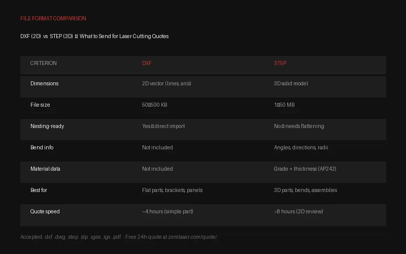
Head-to-Head Comparison
Criterion
DXF
STEP
Dimensions
2D only
3D solid model
File size
50-500 KB
1-50 MB
Nesting-ready
Yes
No (needs flattening)
Bend info
No
Yes
Standard
De facto (Autodesk)
ISO 10303
Material data
No
Yes (AP242)
Quote turnaround
~4 hours (simple part)
~8 hours (3D review)
Best for
Flat parts, simple profiles
3D parts, bends, assemblies
Common File Preparation Mistakes That Delay Quotes
After processing 10,000+ customer files, these are the issues that most frequently add quoting time. Fix them before you send and you will typically get a quote back in under 4 hours.
Missing Material Specification
A DXF with no material callout is the single biggest quoting bottleneck. We need to know: grade (304, 316L, Q235, 6061-T6), thickness in millimeters, and surface finish (mill, No.4, No.8, PVD). Without this, our engineers have to ask — and every round-trip email adds 12-24 hours. Include material specs in the filename, a separate PDF, or email body.
Tolerances Not Called Out
If your drawing has no tolerance block, we default to our standard laser cutting tolerance of ±0.1 mm for features under 300 mm and ISO 2768-m for general dimensions. If you need ±0.05 mm on a specific bore or edge, mark it explicitly. We can hold it — but we need to know.
Threaded Holes and Tapped Features
Laser cutting cannot produce internal threads. If your part has holes that need tapping (M3, M4, M6, etc.), note the thread size and pitch on your drawing. We handle tapping as a secondary operation after cutting — but only if we know about it at quoting stage. Retrofitting tapped holes after parts are cut adds cost and lead time that could have been avoided.
Multiple Parts in One File
We love receiving multi-part assemblies. But please separate individual components onto labeled layers or sheets. A single DXF with 15 unlabeled outlines on one layer requires our team to manually separate and identify each part — adding quoting time. Best practice: one part per layer, layer name = part number, all at 1:1 scale.
Which Should You Send to Zemlaser?
The answer depends on your part — here is our engineering team recommendation:
Send DXF when:
Your part is flat (no bends, no 3D features)
You already have a nested layout or want us to optimize material utilization
You need the fastest possible quote turnaround
You are reordering a part we have cut before
Send STEP when:
Your part has bends, multiple processes, or assembly steps
You want a manufacturability review (we will flag issues before cutting)
This is a first-time RFQ and you want our engineers to fully understand the design intent
You are quoting a multi-part assembly or weldment
Send Both for the Best Experience
The fastest, most accurate quotes come when you send both DXF + STEP. The STEP file gives us 3D design intent and bend information. The DXF file lets us nest and price material immediately. This combination typically delivers a quote in under 4 hours. For high-volume production runs, also include a PDF drawing with tolerance callouts and material specifications.
No CAD file at all? Send a hand sketch with dimensions — we will create the DXF for you. Free CAD support is included with every quote. This is part of what factory-direct means at Zemlaser: no middleman, no red tape, just an engineering team that solves problems.
DXF . DWG . STEP . IGES . PDF accepted | 1-piece MOQ | No obligation
Frequently Asked Questions
Can I send a PDF drawing instead of a CAD file?
Yes. If your PDF includes dimensioned views at 1:1 scale (or clearly stated scale), our engineers can recreate the geometry. For simple flat parts, this adds minimal time. For complex 3D parts with bends, a STEP file is strongly preferred — recreating 3D geometry from 2D PDF views takes longer and introduces interpretation risk.
My DXF file will not open – what should I check?
The most common causes: (1) The file was exported at the wrong DXF version — use AutoCAD 2010 DXF or later. (2) The geometry contains blocks or XREFs that were not exploded before export. (3) The file uses splines that need to be converted to polylines. If your file will not open, email it anyway — our CAM software handles most DXF variants, and if it cannot, we will tell you exactly what to fix.
What STEP application protocol should I use?
STEP AP214 or AP242 are preferred because they include color, layer, and GD&T information. STEP AP203 works fine for basic 3D geometry but carries less metadata. All three are accepted. If your CAD software gives you a choice, pick AP242 — it is the most complete.
Do you sign NDAs for proprietary designs?
Yes. All customer CAD files are treated as confidential intellectual property. We sign mutual NDAs as standard practice, and our privacy policy specifically covers CAD data protection (Section 3: CAD File and IP Protection). Your designs are never shared with third parties, used as samples for other customers, or retained beyond the project lifecycle without your written consent.
Ready to send your files?
DXF or STEP — upload your drawing and get a free quote in 24 hours.
Fiber Laser vs Plasma vs Waterjet: The Complete Comparison
PublishedJuly 2026 Read8 min
Choosing the right cutting technology isn’t a classroom exercise — it’s a per-part cost decision that impacts your lead time, edge quality, secondary processing budget, and ultimately your margin. Three processes dominate industrial metal cutting: fiber laser, plasma, and waterjet. Each has a clear sweet spot. At Zemlaser, we run 10+ fiber lasers daily and regularly advise B2B buyers on when to use which process — including when the best answer isn’t laser at all.
Fiber Laser Cutting: Precision at Speed
Fiber lasers amplify light through doped optical fibers, delivering a focused beam with exceptionally high power density. The result: clean, narrow kerfs at high feed rates on sheet and plate up to 150 mm in stainless steel.
How It Works
A solid-state laser source (1–20 kW typical) pumps light into a doped fiber. The amplified beam exits through a cutting head with assist gas — oxygen for mild steel, nitrogen for stainless and aluminum. The gas ejects molten material and cools the kerf edge. Because fiber lasers operate at a wavelength (~1.07 μm) that metals absorb efficiently, they cut reflective materials (aluminum, brass, copper) that CO₂ lasers struggled with.
Fiber Laser Advantages
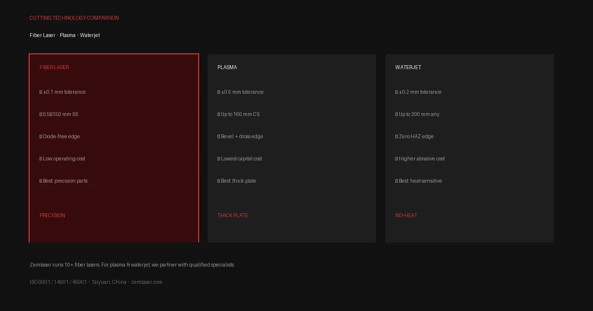
Tight tolerances: ±0.1 mm standard, ±0.05 mm achievable on thin sheet. Compare that to ±0.5 mm typical for plasma.
Excellent edge quality: Nitrogen assist produces oxide-free, weld-ready edges on stainless — no secondary grinding needed.
Thin-to-thick range: One machine cuts 0.5 mm shim stock and 150 mm boiler plate. No process changeover.
Speed: Up to 40 m/min on thin sheet. A 3 mm stainless bracket cuts in seconds.
Low heat input: Small HAZ (heat-affected zone). Minimal distortion. No micro-cracking.
Reflective metal capable: Modern fiber lasers include back-reflection protection, making aluminum, brass, and copper routine.
Operating cost: No consumables beyond assist gas and nozzles. Electrical efficiency 30–40% (vs. 10% for CO₂).
Fiber Laser Limitations
Thickness ceiling: 150 mm stainless / 80 mm carbon steel. Beyond that, plasma or waterjet.
Not ideal for materials that melt rather than vaporize cleanly (some plastics, composites).
Initial capital cost is higher than plasma — but per-part cost is lower at volume.
Best for: Precision sheet metal parts, brackets, enclosures, panels, flanges, gussets — from prototype to 100,000+ production run. This is where Zemlaser’s 10+ fiber lasers operate daily for OEM and export B2B orders.
Plasma Cutting: Thick Plate Economics
Plasma cutting ionizes a gas (compressed air, nitrogen, or oxygen) through a constricting nozzle to create an electrically conductive plasma arc reaching 20,000°C+ (Wikipedia: plasma cutting). The arc melts the workpiece, and the high-velocity gas jet blows the molten metal through the kerf.
Plasma Advantages
Thick plate capability: Cuts 160 mm+ carbon steel. Industrial plasma tables handle plate thicknesses no laser can touch.
Low equipment cost: A capable plasma table is 1/3 to 1/5 the capital investment of an equivalent-power fiber laser.
Forgiving on material condition: Rust, mill scale, and light paint don’t significantly affect cut quality — unlike laser, which needs clean surface for consistent coupling.
Bevel cutting: Plasma torches can be angled for weld-prep bevels — a feature laser cutting heads don’t offer.
Plasma Limitations
Tolerance: ±0.5 mm typical. Expect edge bevel of 1–4° depending on material thickness. Not suitable for precision-fit parts.
HF (High Frequency) start: Traditional plasma uses HF ignition that can interfere with CNC electronics. Modern “blowback” start torches mitigate this.
HAZ and dross: Larger heat-affected zone. Bottom-edge dross requires grinding or chipping for many applications.
Minimum thickness: Below 3 mm, plasma struggles — the arc wanders, kerf width becomes a significant fraction of material thickness, and distortion is severe.
Best for: Heavy steel fabrication — machine frames, structural beams, shipbuilding plate, bridge components. When you need 40 mm carbon steel cut fast and edge bevel is acceptable, plasma wins on cost.
Waterjet Cutting: Cold, Universal
Waterjet cutting uses a 4,000-bar (60,000 psi) water stream mixed with garnet abrasive. There is no heat — material is removed by supersonic erosion. The waterjet cutting process is governed by ISO 9013 tolerance standards for thermal and non-thermal cutting. Because there’s no thermal input, there’s zero HAZ, no microstructural change, no warping, and no oxide layer.
Waterjet Advantages
Any material: Metals, stone, glass, ceramics, composites, rubber, plastics, laminates, food. Thickness up to 200 mm in steel.
Zero heat: No HAZ. No hardening. No distortion. Critical for titanium aerospace components, tool steels that cannot see any thermal cycle, and multi-layer laminates.
No material property changes: Cut edge retains base material hardness and grain structure. No recast layer. No micro-cracks.
Stack cutting: Multiple sheets can be stacked and cut simultaneously — offsetting the slower per-part cycle time.
Narrow kerf: 0.5–1.5 mm typical, comparable to laser on thin stock.
Waterjet Limitations
Speed: Significantly slower than laser on thin sheet. A part that takes 30 seconds on fiber laser might take 3 minutes on waterjet.
Operating cost: Garnet abrasive is a consumable. Pump seals and mixing tubes wear and require regular replacement.
Wet process: Parts and work area are wet post-cut. Requires drying before welding or coating. Some materials (mild steel) flash-rust if not dried promptly.
Taper: Waterjet kerfs exhibit a slight V-shape (wider at top). Modern dynamic tilt heads compensate, but taper remains a consideration on very thick stock.
Best for: Aerospace titanium, thick tool steels, multi-material stacks, stone countertops, glass art, composite trimming — any application where heat is unacceptable or the material range exceeds what thermal processes can handle.
Head-to-Head Comparison
Criterion
Fiber Laser
Plasma
Waterjet
Max SS thickness
150 mm
80 mm
200 mm
Tolerance
±0.1 mm
±0.5 mm
±0.2 mm
Edge quality
Excellent
Fair (bevel + dross)
Good (no HAZ)
HAZ
Minimal
Significant
Zero
Speed (3mm SS)
~25 m/min
N/A (min 3mm)
~0.3 m/min
Materials
Metals only
Conductive metals
Any material
Operating cost
Low-medium
Low
High (abrasive)
Reflective metals
Yes (modern)
No
Yes
How to Choose: A Decision Framework
Choose Fiber Laser When:
Material is metal and thickness is ≤150 mm stainless / ≤80 mm carbon steel
Edge quality and ±0.1 mm tolerance are gating requirements
Volume is medium to high — per-part cost drops with speed
Parts require minimal secondary finishing (no deburr, no grinding)
You need quick-turn prototyping AND scalable production from the same process
Choose Plasma When:
Material is thick carbon steel (>40 mm) where edge bevel is acceptable
Per-part cost is the dominant decision factor
Material surface condition is poor (rust, scale) and you don’t want to pre-clean
You need weld-prep bevel cuts in a single pass
Part tolerances above ±0.5 mm are acceptable
Choose Waterjet When:
Material is not metal — stone, glass, composite, rubber
Material is heat-sensitive — titanium aerospace, hardened tool steel, titanium alloys
No HAZ is an absolute requirement (aerospace, medical implant, nuclear)
You’re cutting very thick stock (>150 mm) regardless of material
Multiple stacked sheets can offset the slower per-part speed
Why Zemlaser Standardized on Fiber Laser
We operate 10+ fiber laser machines ranging from 1 kW to 20 kW on a single factory floor in Taiyuan, Shanxi, China. Our manufacturing capabilities span 0.5 mm shim stock to 150 mm stainless steel plate. For 90% of the metal materials our B2B export clients order — stainless 304/316L, carbon steel, aluminum, titanium — fiber laser delivers the optimal balance of precision, speed, and per-part economics.
When a project exceeds our laser envelope — thick structural plate, exotic non-metal materials, or zero-HAZ titanium — we partner with qualified plasma and waterjet specialists to offer a complete solution. One PO. One point of contact. No process finger-pointing.
Our ISO 9001/14001/45001 certified quality system applies regardless of the cutting method. See our About page for factory details and terms of service for order terms including our standard 7-day FOB Tianjin lead time.
Have a part and not sure which process fits? Upload your drawing — our engineers will recommend the right method and quote within 24 hours. DXF, DWG, STEP, PDF accepted. Free. No obligation.
Frequently Asked Questions
Is fiber laser more expensive than plasma?
Per-part, fiber laser is often cheaper at volumes above 50–100 units because speed and edge quality eliminate secondary grinding and deburring. Plasma has a lower machine hourly rate but the total cost per finished part — including labor for dross removal and tolerance correction — frequently favors laser for sheet-metal-gauge work. For thick structural plate (>40mm), plasma wins on total cost.
Can I get waterjet-quality edges from laser cutting?
On metals, yes — for most applications. Nitrogen-assisted fiber laser produces clean, oxide-free edges that require no post-processing. The difference matters only in niche cases: titanium parts that will undergo subsequent heat treatment, tool steels sensitive to any thermal cycle, or materials where the microscopic recast layer (typically 5–20 μm on laser) is unacceptable. In those cases, waterjet is specified for zero thermal influence.
What file formats do you need for a quote?
We accept DXF, DWG, STEP, IGES, and PDF. For laser cutting specifically, a 2D DXF at 1:1 scale in millimeters is ideal for flat parts. For parts requiring bending or multiple processes, send a STEP file so our engineers can assess the full 3D geometry. Read our DXF vs STEP guide for details.
Can you handle both prototyping and production?
Yes. Our 1-piece MOQ means we’ll cut a single prototype part for your approval. The same fiber laser machine and QC process that cut your prototype also run your 10,000-piece production order. No process drift. No requalification. See our laser cutting services for full capability details.
Need parts like these cut?
Send your DXF or STEP file — free quote in 24 hours, factory-direct pricing.